Wind Chimes Part II:


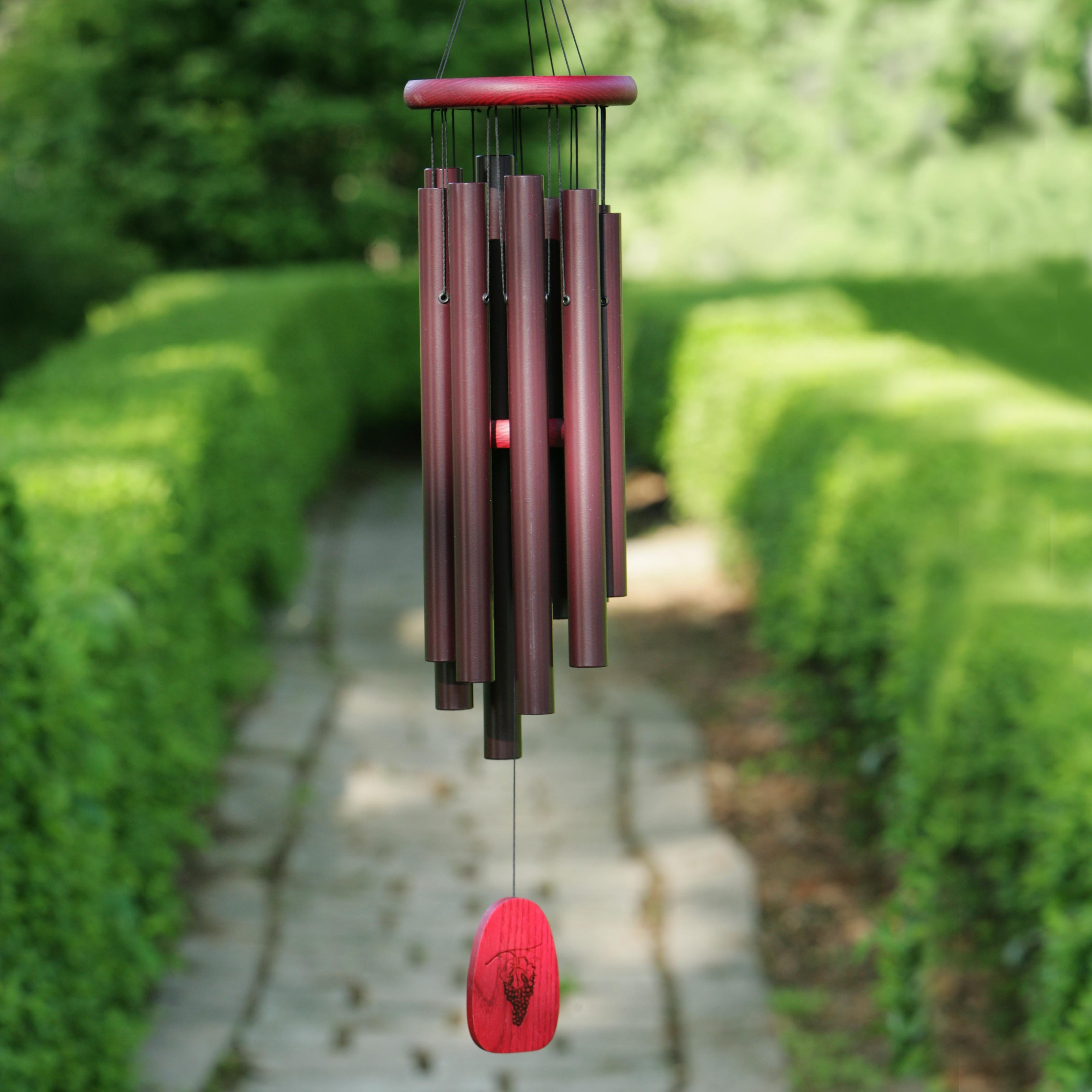
The picture of a set of typical wind chimes has been
obtained from the above-mentioned website. It consists of (apart from lots of string!):
a) the top support ring
b) the striker (or 'clapper') (just visible in the exact middle)
c) the tubular chimes, and
d)
the wind sail (or pendulum bob) (right at the bottom).
A schematic of the wind chimes is given below:
In the previous part, the formula for the maximum height
that a pendulum bob attains with a horizontal force F was derived. The actual
wind chimes consist of a striker (or clapper), in addition to the wind sail (or
flat pendulum bob), so the geometry has to be taken into account. That means a
bit of trigonometry is unavoidable. The schematic of the wind chimes is as
above.
The length of the string from the top support ring to the
centre-of-mass of the wind sail is L, and from the ring to the striker is L’.
The tubular chime is a radial distance x’ away from the centre of the support
ring, and the striker (a circular disk of radius xs) is shown at an
angle q away from the equilibrium
position, when it is just touching the chime. Both the wind sail and the
striker trace circular arcs, since the lengths L and L’ are constant.
When the striker just touches the chime, the following
equation applies (from trigonometry):
L’ sin(q)
+ xs cos(q) =
x’
Because the line segment x’m accounts for the 1st
term of the left-hand side, while the striker (tilted at angle q) radius accounts for the
2nd term.
In addition, we have:
z = cos(q)
= 1 – (hm/L)
and:
sin(q)
= xm/L
Also we have the relation:
(L – hm)2 + x2 = L2
After a little algebra, the above 3 equations becomes a
quadratic:
z2[xs2 + (L’)2]
-2x’xs z – [(L’)2 - (x’)2] = 0 Eqn.1
From the previous section we have:
cos(q)
= 1 – (hm/L) and: hm/L
= 2/[1 + (mg/F)2]
Which can be rearranged as:
z = cos(q)
= 1 – [2/[1 + (mg/F)2]]
This equation can be recast as:
F/mg = [(1-z)/(1+z)]1/2 Eqn.2
The horizontal force on the wind sail (of area A) due to the
wind pressure (wind speed v) is:
F = rv2A/2 Eqn.3
Using these three equations, and substituting values for the
materials and the dimensions for both sets of wind chimes, we get the
following:
|
|
bamboo chimes
|
metal chimes
|
|
L (cms)
|
57
|
75
|
|
L’ (cms)
|
17
|
20
|
|
xs (cms)
|
2
|
3
|
|
x’ (cms)
|
4
|
3.5
|
|
rs
(gm/cc) striker density
|
0.5
|
8
|
|
Vs (cc)
striker volume
|
9.6
|
20
|
|
ms (gms)
striker mass
|
4.8
|
160
|
|
Asail (cm2)
wind sail area
|
32
|
40
|
|
V (km/hr)
min.wind speed for chiming
|
4.3
|
10.3
|
Clearly the wind chimes made of metal require a higher wind
speed than the bamboo wind c- as expected – even though the clearance x’-xs
is much less for the metal chimes.
The wind speed that is obtained is reasonably close to what
I notice: the wind chimes do not sound unless the wind speed is considerable –
which does not happen that often in Delhi. I am not sure of the exact
percentage, but I think it is pretty low (<5 o:p="" of="" the="" time="">
Neighbor’s envy:
One heartening (or annoying) feature is that on many days
that my wind chimes are mute, the neighbor’s wind chimes are pealing away. Why?
Maybe because the neighbor has picked the right orientation with respect to the
prevailing wind direction? Or, more likely: the neighbor’s wind chimes are on
the 4th floor (mine are only on the 1st floor).
As height increases, so does wind speed (the ‘wind profile’):
The relationship is a power law, with an exponent of
approximately 1/7. This is called the Hellman coefficient, and varies from 1/7
depending upon the flatness of the terrain, upon whether the wind profile is over land or over water, etc. (range: 0.06
to 0.60). Rough terrain results in a lower wind speed near the ground.
So if my neighbor’s chimes are on the 4th floor,
the wind speed at that height is (4)0.143 = 1.21X. On many days,
that 21% difference may well account for the fact that my chimes are mute,
while the neighbor’s are clearly audible. And, the Hellman exponent may be different from 0.143(1/7).
Limitations:
(i)
The orientation factor (cos(f)) has been mentioned
above.
(ii)
Ideally, the wind speed should be measured with
an anemometer, and the weights and dimensions accurately measured. Better
still, the experiment should be done in a wind tunnel! For example, do the different cylindrical chimes (tubes) affect each other? Here, a single tube is considered, and that is a reasonable approximation, but does the number of chimes (tubes) matter?
(iii)
The wind sail (or pendulum bob) area has been
taken straight off in the calculation, but the effective area may not be
exactly the same as the geometrical area.
(iv)
It is assumed above that the tubular chimes do
not move. Clearly, the pressure due to the wind will act on the chimes also.
The effective area of the cylindrical chimes is half that of the wind-facing
surface area, but the length of the tube may be significant. To make the motion
negligible, the weight of the chimes would have to be significant, which can be
ensured by increasing the thickness of the tube. Since bamboo is much less
dense, this error would be more significant for the bamboo chimes.