Tuesday, November 17, 2015

bottle...contd:

I just wanted to add one point: energy is a scalar.
Even a half-full bottle lying on its side with the water in the bottom half, like so:
the above analysis still applies (with the caveat about the actual hydrodynamics), the only difference being that the length of the bottle is replaced with its width.

Moving on, somewhat:
That's the top view of a donut - assumed to be torus, with a circular cross-section, and a circular hole.
Why am I looking at donuts? Because:“Between the optimist and the pessimist, the difference is droll.
The optimist sees the doughnut, the pessimist the hole!” – Oscar Wilde               
Firstly, many doughnuts do not have holes at all. That would imply that pessimists would, perforce, have to eat only doughnuts with holes. Secondly, the sizes of doughnuts – even in the age of cookie-cutter standardization – are not fixed. Nor are their shapes clearly toroidal: or, not clearly having circular cross-sections.
Contrast Wilde’s statement with the more common characterization of the optimist as seeing a glass as half-full, and the pessimist as seeing it as half-empty.
Typical dimensions of a doughnut:
outer diameter: do = 9.4 cms
inner diameter: di = 2.7 cms
fill factor ff = (do)2/[(do)2 + (di)2]
= 0.924
Note: one could calculate a volume ratio, and this would give a different number. The volume of the doughnut is: V = Ac, where A is its cross-section and c is its circumference. The cross-section is:
A = pr2, where r = (ro – ri)/2 = 4.7 – 1.35 = 3.35 cms.
A = 35.26 cm2
The circumference is: c = 2pR, where R = (ro + ri)/2 = (4.7 + 1.35)/2 = 3.025 cms
C = 19.01 cm
Vd = (35.26)(19.01) = 670.29 cm3
Total volume is: Vt = (pR’2)(2r), where R’ = R + r = 3.025 + 3.35 = 6.375 cms
 = 855.43 cm3
Volume fill factor = (Vd)/( Vt) = 0.783

Clearly, Wilde has slanted his definition against a putative pessimist, making his/her job much more difficult. His definition is, of course, the area fill factor and not the volume fill factor.
Not that Wilde was an unabashed optimist: the author of “The Portrait of Dorian Gray” or “Salome” had a clear view of the dark side. It is more likely that he just couldn’t resist the aphorism. 

Of course, the volume fill factor is ambiguous: it could probably be defined differently.
But then, ambiguity was Wilde's forte! 


Thursday, November 12, 2015

I was walking in the park with a water bottle in my bag, and some of the water in it had already been consumed. I noticed that the half-empty bottle made a bit of a sloshing gurgling sound as I walked along. So naturally I wondered what fraction of the bottle should be full for it to make the most sound?
Note the proverb that "empty vessels make the most sound."
However, like a midgap trap has the highest recombination rate, so intuitively one might expect that a half-empty bottle would make the loudest sloshing sound.
The following argument is original - although I discussed it with my friend Tirthankar Haldar - and he gave me valuable feedback and suggestions. The usual rules apply: any remaining error is only due to me.

Consider the bottle is a cylinder of area A and length d.

The water in it is filled to a length x., and its density is r, and it is subject to acceleration g.


The sound produced by the water is proportional to the energy, and the energy is given by:

                                                   E = rgAx(d - x)

The motivation for this energy is the mass of the water (rAx ) multiplied by the acceleration g and by the distance the water can move: d-x.

The force is given by the negative of the derivative w.r.t.x:
                                                    F= - rgA(d - 2x)

Differentiating again and putting the derivative it to zero gives: x = d/2.
That is, the half-empty bottle would make the most sloshing sound.
The restoring force is of the form: F = kx, not the usual F= - kx, that is characteristic of simple harmonic motion. That implies that the sloshing frequency w = Ö(k/m) is imaginary and that the sloshing is damped i.e. it dies out exponentially.

a) Clearly the above argument rests - or falls - depending upon the validity of the energy expression given above for the sloshing motion of the water in the bottle. 
b) It is also assumed that the sloshing sound is a maximum exactly when the sloshing energy (as defined above) is maximum - which need not necessarily be the case.
c) The initial condition assumed above (see figure) is a bit odd. If a bottle is horizontal, the top half should be empty, not the right side! However, this kind of an initial condition could be achieved if one starts with a half-empty vertical bottle and turns it upside down. Or turns it to any angle other than the horizontal! So the diagram above should be rotated clockwise by 90 degrees - but I'm not gonna do it!

Ok, so this argument may be fatally flawed. 
Never mind, Milord, I rest my case - and if the defendant is guilty of stupidity as charged, so be it!


Wednesday, September 23, 2015

More trivia:

Green sunshade and shadow
Observation:
There is a bus-stop with a green sunshade on Lancer’s Road that I pass every day. On sunny mornings, I noticed that the shadow under the sunshade was greenish. What was less clear was this: the green hue was most visible when I was some distance away and looking at the bus stop. But the closer I got to the bus stop, the fainter the green became – until it was barely noticeable when I was just under the sunshade. As I walked away from the bus stop, the same sequence occurred, in reverse. When I was again some distance away, the green shadow again became visible.
This puzzling green shadow did not occur on cloudy days, or in the afternoon. So clearly it had something to do with the direct sunshine falling on the sunshade, and not on diffuse scattered sunlight.
The 'sunshade' is standard green fibreglass.


Possible explanation:
a) the fibreglass looks green in reflection because all other colours are absorbed.
b) in transmission, which is what gives the green shadow, the incident, unabsorbed green light is scattered.


When sunlight is incident vertically on the sunshade, it traverses the minimum thickness t of the sunshade.
When the ray is incident at an angle q to the vertical, it passes through a thickness t /cos (q). This is, as expected, a minimum value t for q = 0, and increases as q increases.
So as the ray becomes more oblique, it passes through a greater thickness of the sunshade and becomes a darker green.
When I observe the ground under the sunshade from a distance, the rays that are visible to the eye are oblique and dark green, and when I am directly under the sunshade, the rays are vertical, and a very pale green.
This assumes that the sunshade is made of a homogenous translucent material and that it is optically isotropic.
According to the link:

polyethylene and fiberglass tend to scatter light, while acrylic and polycarbonate tend to allow radiation to pass through directly.

The angle of the ray determines the amount of scattering (because of t/cos(q)) and the more intense green occurs at oblique angles of incidence.

The amount of light transmitted through the sunshade is given by:

t = exp(- (αs+ αa) l )

where l = t/cos(q) is the path-length of the ray, αs is the scattering coefficient and αa is the absorption coefficient. For green, αa = 0, and αs ¹0, while for other colours in the visible αa ¹0.

The scattering through the sunshade is exactly analogous to the enhancement of the redness of sunset rays as the sun dips below the horizon, due to the increased path-length of the oblique sun-rays.


Saturday, September 5, 2015

Ok, so 9 months later here are a few corrections, as promised:
Corrections:
(i)                  Including the mass of striker (by just adding it to the mass of the wind sail):
a)      Metal striker: R= 20 mm & t = 8 mm
Ms = r (pr2t) = 8 (3.14)(22)(0.8) = 80 gms = 0.08 kg
Without including the mass of the striker the min speed is:  2.86 m/s i.e. 10.3 kph
Including the mass of the striker, the min speed is: 3.5 m/s i.e. 12.6 kph
b)      Bamboo striker:
Similarly,
Ms = r (pr2t) = 0.5 (3.14)(22)(2.2) = 13 gms = 0.013 kg

Without including the mass of the striker the min speed is:  1.21 m/s i.e. 4.34 kph
Including the mass of the striker, the min speed is: 2.38 m/s i.e. 8.56 kph

Note: if the striker mass is included, the effective length L should decrease, because of a shift in the position of the centre of mass – but luckily it does not come into the formulas at all!


(ii)                 Chimes were assumed to be immobile: how good is that approximation, or is it even valid?

Effective area of chime:  Ach = prL/2 = (3.14)(0.85)(36)/2 = 48.0 cm2
Volume of chime: Vch = p [(r1 )2-(r2)2] L = (3.14)(0.852 – 0.702) = 26 cc
Mass of chime mch = r Vch = (8)(26) =210 gms = 0.21 kg
Force of gravity on chime: F = mg = (9.8)(0.21) = 2.06  Nt
Force due to wind at 10 kph (2.78 m/s):  F =  Ach ( rair v2)/2 = (0.0048)(1.2)(2.78)2/2  =  0.022   Nt
F/mg = 0.022/2.06 = 0.0108
mg/F = 92.6
h = 2L/(1 + 92.62) = 2(0.75)/8573 = 1.75x10⁻⁴ m = 0.175 mm.
Tan(q/2) = F/mg = 0.0108 q = 1.24°.
For a chime, the centre of mass is at L/2, so this height and angle should be half (0.088 mm and 0.62°).
(iii)               Angular issues:

Another issue which was not mentioned earlier is the angular factor, taking into account the number of chimes. In the metal chimes that I have, there are 5 chimes, so that a top view  would show a 72° angular separation between adjacent chimes when they are at rest. The bamboo chimes have 6 chimes, so the angular separation between adjacent chimes is 60° (as shown in the above figure). In the preceding derivation, the striker is assumed to move away from the centre along a radius, and it is also assumed that the chime is also located on the same radius – a case of motion along a line. However, the striker may also move in a direction that takes it along a radius that is midway between two adjacent chimes – or, indeed, at an arbitrary angle. The displacement xm was earlier calculated using the linear case. The most general case, if the striker moves at an arbitrary angle, is more difficult – but the case in which it moves midway between two adjacent chimes is not so tough. In the above figure, the striker (of radius s) moves a distance d, till it hits both chimes (of radius c) simultaneously. In the figure above, there are 6 chimes, so the positions of the chimes are separated by 60°.
In the case of linear motion (discussed previously), the condition for the striker to touch the chime is:
d1 + s + c = r
where r is the radius of the circle on which the centres of the 6 chimes are located.
Now consider the case in which the striker moves midway between adjacent chimes in the figure above. Using the cosine law, the condition for the striker to touch both chimes at once is:
(s+c)2 = (d2)2 + r2 – 2d2r  cos(q)
where 2q = 60°.
One can plug in the numbers for s, c and r and solve the quadratic to obtain the displacement d. This can displacement then be put into the previously calculated xm and find the wind-speed that will cause contact between the striker and the chime.
Solving the quadratic:
d2 = - rcos(q) + ((rcos(q))2 + (s+c)2)1/2
Is d1 or d2 greater? That depends on the specific values of r,s,c and q - it could go either way.

If the displacement required is greater in the midway case (d2) than it is in the linear case (d1), then the wind-speed is also higher in the midway case (and vice versa). For the case of 6 chimes, the plot of v(q) should exhibit six-fold symmetry; and for 5 chimes, it will exhibit five-fold symmetry.
(iv)              Miscellaneous:
Here it is assumed that the material of the chimes, the striker, and the wind sail (bob) are all the same. To alleviate this problem, the density of the bob & striker should be lower than that of the chimes. Apparently, the material of the striker is different, but the chimes and the bob seem to be of the same material in the metal chimes.
The Bali bamboo chimes have another odd problem: the chimes are not kept hanging vertically down: they are at about 10-15° away from the vertical, pointing radially outward from the bob/striker at the centre. 


Saturday, May 2, 2015

Wind Chimes Part II:


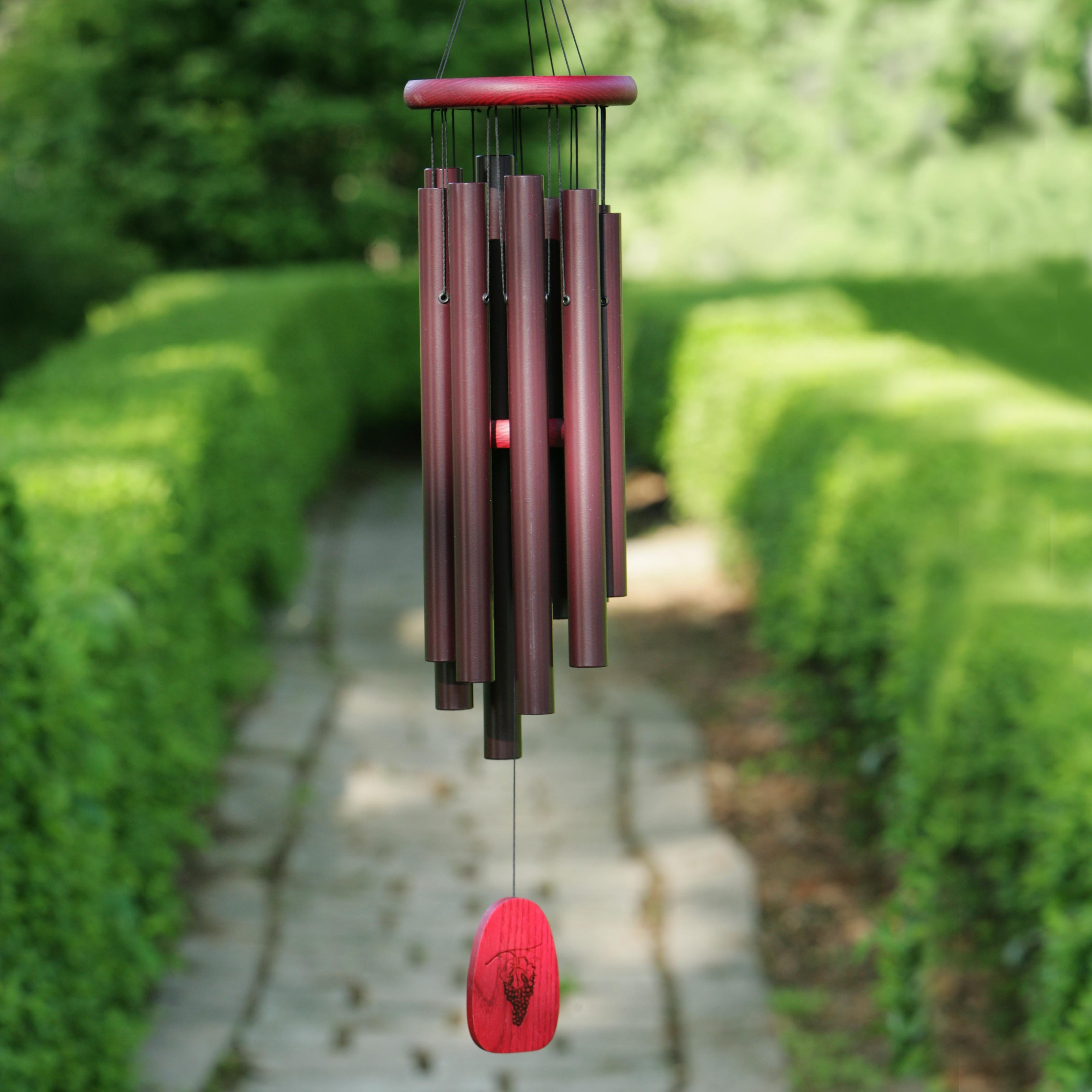
The picture of a set of typical wind chimes has been obtained from the above-mentioned website. It consists of (apart from lots of string!):
a) the top support ring 
b) the striker (or 'clapper') (just visible in the exact middle) 
c) the tubular chimes, and 
d) the wind sail (or pendulum bob) (right at the bottom).

A schematic of the wind chimes is given below:

In the previous part, the formula for the maximum height that a pendulum bob attains with a horizontal force F was derived. The actual wind chimes consist of a striker (or clapper), in addition to the wind sail (or flat pendulum bob), so the geometry has to be taken into account. That means a bit of trigonometry is unavoidable. The schematic of the wind chimes is as above.
The length of the string from the top support ring to the centre-of-mass of the wind sail is L, and from the ring to the striker is L’. The tubular chime is a radial distance x’ away from the centre of the support ring, and the striker (a circular disk of radius xs) is shown at an angle q away from the equilibrium position, when it is just touching the chime. Both the wind sail and the striker trace circular arcs, since the lengths L and L’ are constant.
When the striker just touches the chime, the following equation applies (from trigonometry):
L’ sin(q) + xs cos(q) = x’
Because the line segment x’m accounts for the 1st term of the left-hand side, while the striker (tilted at angle q) radius accounts for the 2nd term.
In addition, we have:
z = cos(q) = 1 – (hm/L)
and:
sin(q) = xm/L
Also we have the relation:
(L – hm)2 + x2 = L2
After a little algebra, the above 3 equations becomes a quadratic:
z2[xs2 + (L’)2] -2x’xs z – [(L’)2 - (x’)2] = 0         Eqn.1
From the previous section we have:
cos(q) = 1 – (hm/L)  and: hm/L = 2/[1 + (mg/F)2]
Which can be rearranged as:
z = cos(q) = 1 – [2/[1 + (mg/F)2]]
This equation can be recast as:
F/mg = [(1-z)/(1+z)]1/2      Eqn.2
The horizontal force on the wind sail (of area A) due to the wind pressure (wind speed v) is:
F = rv2A/2               Eqn.3
Using these three equations, and substituting values for the materials and the dimensions for both sets of wind chimes, we get the following:

bamboo chimes
metal chimes
L (cms)
57
75
L’ (cms)
17
20
xs (cms)
2
3
x’ (cms)
4
3.5
 rs (gm/cc) striker density
0.5
8
Vs (cc)
striker volume
9.6
20
ms (gms)
striker mass
4.8
160
Asail (cm2)
wind sail area
32
40
V (km/hr)
min.wind speed for chiming
4.3
10.3

Clearly the wind chimes made of metal require a higher wind speed than the bamboo wind c- as expected – even though the clearance x’-xs is much less for the metal chimes.
The wind speed that is obtained is reasonably close to what I notice: the wind chimes do not sound unless the wind speed is considerable – which does not happen that often in Delhi. I am not sure of the exact percentage, but I think it is pretty low (<5 o:p="" of="" the="" time="">

Neighbor’s envy:

One heartening (or annoying) feature is that on many days that my wind chimes are mute, the neighbor’s wind chimes are pealing away. Why? Maybe because the neighbor has picked the right orientation with respect to the prevailing wind direction? Or, more likely: the neighbor’s wind chimes are on the 4th floor (mine are only on the 1st floor).
As height increases, so does wind speed (the ‘wind profile’):

The relationship is a power law, with an exponent of approximately 1/7. This is called the Hellman coefficient, and varies from 1/7 depending upon the flatness of the terrain, upon whether the wind profile is over land or over water, etc. (range: 0.06 to 0.60). Rough terrain results in a lower wind speed near the ground.
So if my neighbor’s chimes are on the 4th floor, the wind speed at that height is (4)0.143 = 1.21X. On many days, that 21% difference may well account for the fact that my chimes are mute, while the neighbor’s are clearly audible. And, the Hellman exponent may be different from 0.143(1/7).

Limitations:

(i)                  The orientation factor (cos(f)) has been mentioned above.
(ii)                Ideally, the wind speed should be measured with an anemometer, and the weights and dimensions accurately measured. Better still, the experiment should be done in a wind tunnel! For example, do the different cylindrical chimes (tubes) affect each other? Here, a single tube is considered, and that is a reasonable approximation, but does the number of chimes (tubes) matter?
(iii)               The wind sail (or pendulum bob) area has been taken straight off in the calculation, but the effective area may not be exactly the same as the geometrical area.

(iv)              It is assumed above that the tubular chimes do not move. Clearly, the pressure due to the wind will act on the chimes also. The effective area of the cylindrical chimes is half that of the wind-facing surface area, but the length of the tube may be significant. To make the motion negligible, the weight of the chimes would have to be significant, which can be ensured by increasing the thickness of the tube. Since bamboo is much less dense, this error would be more significant for the bamboo chimes.

Wednesday, December 31, 2014

Wind chimes Part I


Fig.1
There is a lot of information online about wind chimes. However, I was unable to find an answer to a natural question: is there a critical wind speed below which the wind chimes will not emit any sound?
The key to answering this question is to first find out the response of a pendulum to a constant horizontal force. This is solved as a question at the website:
“A ball of mass m is connected by a strong string of length L to a pivot. A steady wind exerts a constant horizontal force F on the ball as shown. Initially, the ball is held in place with the string vertical. The ball is then released and is observed to swing up and down between it staring point and its maximum height H above its starting point.” - by David Ailion of the University of Utah.
Ailion gives the worked out solution, but does not specifically connect it to the wind-speed v. This is expressed as follows:
                                F = rv2A/2
where r is the density of air and A is the area of the wind-catching surface of the pendulum bob. This assumes that the angle between the normal to the surface and the wind velocity f = 0. If not, this force would be reduced by a cos(f) factor.
                Although Ailion has given the worked-out solution for the equilibrium height and for the maximum height, this is mine; the final equations are the same.
However, the geometry is somewhat different for wind chimes – there is a pendulum bob which catches the wind, but there is also a striker, which is much further up, and is a thin round disk which actually contacts one of the hollow cylindrical chimes, producing the tone that we hear. This geometry is dealt with in the second section, and then applied to the cases of bamboo and iron wind chimes.

Pendulum with constant horizontal force F:
see Fig.1:
a)      Equilibrium height: velocity = maximum
h = L [1 – cos(q)]

Resolve tension T into vertical and horizontal components:
                                T sin(q) = F
                                T cos(q) = mg
                                tan(q) = F/mg
Substituting into equation for h:

h = L{ 1 – [ 1 + (F/mg)2]-1}

If F = 0, the equilibrium position of the pendulum is the standard h = 0 (pendulum hangs vertically down when there is no wind).
If F = mg, h = L/2,
And if F = ¥, h = L.
Note: H.Munera & H.R.Maya Lat.Am.J.Phys.Ed. 5 (2011) 22-30: 'method of apparent vertical' applied to the "perturbation of a dynamical system by a constant or nearly constant force, not necessarily small. The basic idea is to rotate the system of coordinates so that the z-axis coincides with an apparent acceleration of gravity".
(Munera & Maya claim that their method is not the same as the equivalence principle. I was unable to understand why, and it is anyway a finer point that is not relevant here). This gives a vector equation:
g' = g + F/m
The upshot is that the equilibrium position is displaced by an angle q, given by: tan(q) =  F/mg. This gives the same position as derived above, as it must.

b) maximum height: velocity = 0
For a constant horizontal force acting over a horizontal distance x:
                                Fx = mgh
This x is related to the length of the pendulum by:
                                x = L sin(q)
The height h is given by:
                                h = L[ 1 – cos(q)]
Eliminating h we get:
F/mg = [1 – cos(q)]/sin(q) = tan (q/2)
Substituting in the equation for h and doing some algebra, using the half-angle formula:
                                tan(q) = 2 tan(q/2)/[1 – tan2(q/2)]
We finally get the maximum height:
                                h = 2L/[1 + (mg/F)2]
If F = mg, h = L.
If F = ¥,  h = 2L.


Fig.2:


Fig.2 shows the wind blowing with velocity v from L to R, displacing the equilibrium position from the vertical dotted line to the line marked 'eq'. The position 1 corresponds to the maximum height calculated above. The position 2 corresponds to the maximum height on the other side as the pendulum swings.
The equilibrium position is a measure of the energy due to the wind because heq = 0 when F = 0.
Thus the height corresponding to 2 is given by:
                                mg(h1 – h2) = mgheq
When there is no wind heq = 0 and h1 = h2 and the pendulum swings symmetrically about the equilibrium position.
Actually, some of the analysis is not needed for the stated purpose: to find the critical wind speed at which the wind chimes will sound. The only one needed is the one for the maximum height:

                                h = 2L/[1 + (mg/F)2]

However, the actual geometry of the wind chime is somewhat more complicated than a simple pendulum in a wind. There is a bob (which catches the wind) and there is a striker which is higher up, which actually touches the hollow metal cylinders that actually emit the sound on being struck. The actual case is discussed in the second section.


Saturday, September 13, 2014

Light & Height
OK, I’m not anywhere near being Flaubert, so I do not seek the mot juste.
I’m also declaring my independence to blog about the nebulous and quite possibly the trite and the obvious – and to do it shamelessly.
The Sun is largely high in the sky, ignoring sunrises, sunsets and high latitudes.
We tend to replicate this in our homes, although lights are more often on walls than ceilings – and rarely on floors.
Trees (almost) always grow upwards, towards the big light in the sky. They are phototropic.
Height is an advantage – the taller trees have unfettered access to sunlight.
For humans, the taller you are, the farther you see. In the savannah that humans are widely supposed to have grown up in, height would allow one to spot both predators and prey in advance. Of course, one could have climbed up a tree to scan the far horizon – if there happened to be a tree nearby.
In the sea also, a tall captain would help – but sailors solved the problem of spotting storms early by putting a lookout on the mast.
Anyway, the area that can be scanned is directly proportional to the height – of the human or the vantage point.
But the point is that the upward direction is associated with more light and increased viewing area. Conversely, if you are shorter or if you are stuck in a pit or a deep valley, you will have a smaller amount of light and a decreased viewing area. So a downward direction is associated with less light.
An extreme example is the concept of building a very high tower at the South Pole that is permanently in sunshine - or a solar collector in low Earth orbit. Either could be used to generate solar energy.
The tower would be 527 kms high on Earth, assuming a perfectly spherical Earth (for R=6400 and q=22.5°). Of course, you would have to add about 18 kms to the height of the tower, since the polar radius (6353 kms) is less than the mean radius (6371 kms). 
Note: The geometry is obtainable from the gif link mentioned below.


http://theworld.com/~reinhold/lunarpolarfig2.gif